
Introduction to Arduino Temperature Sensors
What is an Arduino?
Arduino is an open-source electronics platform based on easy-to-use hardware and software. It consists of a programmable microcontroller board and a development environment that allows users to write and upload code. This platform is widely popular among beginners and professionals for building interactive projects due to its simplicity and flexibility. Whether you want to create small sensors or complex automation systems, Arduino provides the essential building blocks to bring your ideas to life.
Overview of Temperature Sensors
Temperature sensors are devices that measure temperature and convert it into an electrical signal interpretable by a microcontroller. Among the most common types used in Arduino projects are thermistors, digital temperature sensors, and thermocouples. For beginners, thermistors are often preferred due to their simplicity and reliability. Thermistors are analog sensors that change their resistance based on temperature, which makes them easy to interface directly with Arduino analog inputs. Understanding how these sensors work is the first step toward successfully building a temperature monitoring system.
Essential Components Needed
Arduino Board Selection
Choosing the right Arduino board depends on your project requirements and availability. Popular options for beginners include the Arduino Uno, Nano, and Mega. The Arduino Uno is highly recommended due to its ample analog inputs and large community support. It features an analog-to-digital converter (ADC) that can read voltage variations from sensors like thermistors, enabling precise temperature measurements. Regardless of the model, ensure your board has at least one analog input pin to connect the temperature sensor.
Temperature Sensor Options
For this project, the recommended temperature sensor is an NTC (Negative Temperature Coefficient) thermistor. NTC thermistors decrease their resistance as temperature increases, making them intuitive for beginners to interpret. In contrast, PTC (Positive Temperature Coefficient) thermistors increase resistance with temperature but are less common for basic temperature sensing. Thermistors require fewer complex components and coding adjustments compared to digital sensors, which often use communication protocols like I2C or SPI.
Additional Materials and Tools
Besides the Arduino board and thermistor, you will need a fixed resistor to build a voltage divider circuit, typically close in value to the thermistor’s resistance at room temperature. This resistor ensures measurement accuracy by balancing voltage changes when temperature varies. Other useful materials include jumper wires, a breadboard for easy circuit assembly, and a USB cable to connect the Arduino to your computer. For testing resistance, a multimeter can be very helpful, though Arduino itself can estimate resistance values with simple coding if a multimeter isn’t available.
Step-by-Step Assembly Process
Connecting the Temperature Sensor to Arduino
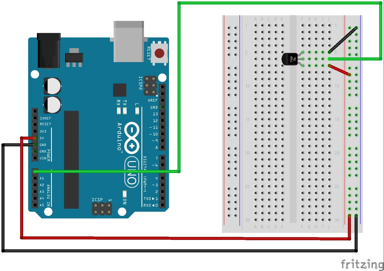
Start by connecting one terminal of the thermistor to the 5V power pin on the Arduino. Then, connect the other terminal of the thermistor to one end of the fixed resistor. The junction between the thermistor and resistor will form the output voltage that changes with temperature. Connect this junction to one of the Arduino’s analog input pins, such as A0. Finally, connect the other end of the resistor to the ground (GND) pin on the Arduino. This setup creates a voltage divider, enabling the Arduino to measure voltage drop across the thermistor.
Wiring Diagram Explained
The voltage divider circuit works by splitting the 5V supply between the thermistor and the fixed resistor based on their resistance ratio. When the temperature changes, the resistance of the thermistor varies, causing the voltage at the junction connected to the Arduino analog input to fluctuate. This voltage is then read by the Arduino’s ADC, converted into a digital value, and used to calculate the actual temperature via mathematical formulas. Ensuring that the resistor value is close to the thermistor’s nominal resistance improves the resolution and accuracy of your measurements.
Programming the Arduino
Writing the Basic Code
To start programming, open the Arduino IDE and create a new sketch. The code should first read the analog value from the input pin connected to the voltage divider. Using the Arduino voltage divider formula, you can calculate the thermistor’s resistance from this analog reading. Afterward, apply the Steinhart-Hart equation, which converts resistance into temperature in Kelvin. Finally, convert this value to Celsius by subtracting 273.15. Make sure to define the Steinhart-Hart coefficients in your code for accurate temperature calculation. Using comments in your code helps clarify each step, especially for beginners.
Uploading and Testing the Sketch
Once the code is ready, connect your Arduino board to your computer via USB and select the correct board and port in the IDE. Upload the sketch and open the Serial Monitor to observe the output readings. You should see temperature values displayed, which update at intervals, typically every 500 milliseconds. This delay is essential to prevent flooding the Serial Monitor and to stabilize sensor readings. If the values appear erratic, double-check your wiring and code logic to ensure the voltage divider and Steinhart-Hart calculations are implemented correctly.
Reading and Displaying Temperature Data
Using Serial Monitor
The simplest way to display the temperature data is through the Arduino IDE’s Serial Monitor. By printing the temperature value to the Serial Monitor, beginners can easily verify sensor functionality without additional hardware. This method also helps in debugging and adjusting the code on the fly. Remember to convert the readings to the desired unit, typically Celsius for most projects. If you prefer Fahrenheit, include the relevant conversion formula, but for a beginner setup, keeping to Celsius reduces complexity.
Optional: Adding an LCD Display
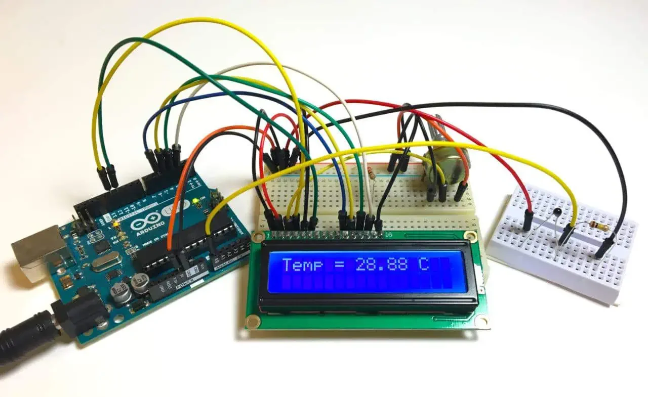
To enhance your project, you can add a 16×2 LCD display to show temperature readings directly on the device. This involves connecting the LCD to the Arduino using several digital pins and utilizing a library such as LiquidCrystal to control the display. When implementing the LCD, ensure your code clears the screen before updating the temperature to prevent overlapping text. This visual feedback is more user-friendly for standalone projects where constant serial monitoring is inconvenient.
Troubleshooting Common Issues
Sensor Reading Problems
If your sensor readings seem inaccurate or unstable, first verify the resistor value used in your voltage divider matches the thermistor’s nominal resistance. Significant mismatches can skew temperature calculations. Additionally, avoid trying to measure the thermistor’s resistance directly with the Arduino without a voltage divider, as this will give unreliable results. Insufficient delays between readings or failing to calibrate with the Steinhart-Hart equation can also cause erratic output. Carefully reviewing these factors often resolves common sensor issues.
Code Errors and Fixes
When your sketch doesn’t behave as expected, look for common coding mistakes. Failing to apply the Steinhart-Hart equation or incorrectly converting temperatures between Kelvin, Celsius, and Fahrenheit units can lead to confusing results. Also, ensure you incorporate proper timing delays to stabilize data and prevent overwhelming the Serial Monitor or LCD. If using an LCD display, make sure the screen is cleared at each refresh to avoid cluttering. Syntax errors or missing library includes are easily spotted through error messages in the Arduino IDE and should be fixed accordingly.
Expanding Your Project
Integrating with IoT Platforms
Once your temperature sensor is working reliably, you can take your project further by connecting Arduino to IoT (Internet of Things) platforms. Using modules like Wi-Fi or Bluetooth shields, your device can send temperature data online for remote monitoring. Platforms such as Blynk, Thingspeak, or MQTT brokers allow you to visualize, log, and analyze data in real-time from anywhere. This step introduces networking concepts and opens opportunities for smart home or environmental monitoring applications.
Adding Data Logging Features
Data logging enhances your temperature sensor by allowing it to record temperature changes over time. By adding components like an SD card module, the Arduino can save temperature readings to external storage. This is useful for long-term experiments or tracking environmental conditions. Implementing data logging requires modifying your code to write data at regular intervals and managing storage space efficiently. Analyzing logged data helps identify trends and provides insights beyond immediate temperature readings.


